
Turning the neck features on the fuselage socket side of the landing gear

Lathe dog is attached to the Ankle / wheel side of the gear leg to give the torque to turn between centers

Tail Stock is off set with live center attached to create the landing gear taper.

overview showing the full setup

taper cut with the X axis in Auto Feed mode

Making a ton of chips, passes are run until taper meets the small end diameter and the black sharpie line on the fuselage / socket side.

Approaching the final cuts

Final gear profile, geometry is similar to an RV leg but thicker due to the legs being made from 2024-T3 rod stock

Ankle leg to axle adapter over all rough cut

corners knocked off to aid in the turning operation.

Ankle setup also turned between centers but with no tail stock off set.

Custom made steady rest with ball bearing guides set up to start the boring process of the part.

early boring bar setup bringing the ID to the finished 1.25″

landing gear sockets also processed on the lathe providing thickness reduction in the low stress / no leg contact areas along with a tooth pastern for the bonding operation. cross bolt bushings are also produced.

Showing the full axle > ankle bracket > Leg > socket setup.

Another view of the leg setup.

Detail view of the ankle bracket

pair of ankle brackets with 4x AN4’s dry fitted

centering, drilling and reaming setup for cross bolt, bushings are bonded to the tube, final step this whole area gets burred in a ton of layups and G10

sockets cleaned and primed with Aeropoxy ES 6228 metal bond epoxy

outside layout on the fire wall, gear come in from the corner at 45º

Preliminary dry fit of the socket.

alignment of the sockets via attaching the legs and brackets, once good to go the inside is tacked in with flox fillets, you can see the folding chair under the plane to help get in the right position.

Flox / Metal bond epoxy fillet added and surface prepped for lamination.

initial 7715 plies

Kevlar 49 energy adsorbing ply

7725 cover ply and peel ply edge treatment

free end of the socket was cut to a bevel angle that intersects with the fire wall, the part is also bonded to the fire wall

initial socket to fuselage connection laminates

cardboard templates and final Carbon diagonal gussets

diagonal gussets aligned

tacking in the diagonal gussets with a Micro / Flox mix

rotary razor cutting some 7715 for cloth kits

diagonal gusset to fuselage layups w/ peel ply edge treatment

inverted setup with some bungee cords for connection safety.

Large surface area Cross bolt G10 plates

thick “fillet G10 plate processing progression

outside bevel and ID processed on the lathe, G10 Machines very well and chips are fairly easy to clean up.


G10 beef up structure for cross bolt

compression bar gusset being fitted, tan masking tape to scribe in the fit with a Sharpie

connection layup
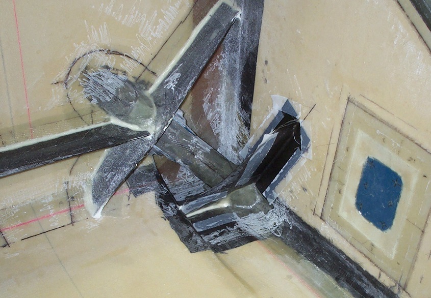
gear drag compression gusset processed

ankle bracket alignment, setup for cross drill

final wheel end of the landing gear assembly

preliminary marks for the tail wheel socket pass thru

Laser left to right alignment of the tail wheel spring & socket

Angle alignment of the tail wheel socket & spring

inside in process view of the backup gusset structures for the tail wheel spring along with much of the H stab pass thru returns & gussets

Milling the tail wheel fork bracket

turning the tail wheel spring to fork adapter.

Near Finished tail wheel assembly

